Ich habe mittlerweile an meinem FabScanner weiter Hardwareumbauten vorgenommen. Mich hat es eine ganze Weile gestört, dass ein Klasse 3a Laserscanner verwendet wird. Klasse 3a ist eine Klasse, die für neue Laser nicht mehr verwendet werden darf. Kurz gesagt ist die Laserstrahlung gefährlich fürs Auge und darf unter anderem für viele Sachen nicht ohne Gehäuse eingesetzt werden. (Es gibt Studien die zeigen, dass auch bei sichtbaren Lasern der Liedschutzreflex nicht immer einsetzt und Schäden ab 0,25s auftreten). Durch die Bauform wird auch der Laserwarnhinweis verdeckt.
Ich habe mir daher bei amazon/Laserfuchs einen Klasse 1 Laser besorgt.
90.jpg)
Bei diesem liegt das obligatorische Heft für Warnhinweise, sowie ein Aufkleber zum anbringen an ein Gehäuse bei. Der Durchmesser ist etwas kleiner, so dass die original FabScan Halterung nicht passt. Und er kostet fast doppelt so viel wie der Watterott Laser ohne dass er eine einstellbare Linse hat.
In dem Zug habe ich direkt einen zweiten Steppermotor verbaut. Neben Steppertreiber und Laser, M3-Schrauben (wie im Orignalprojekt, nur mit zusätzlichem Kühler für den Steppertreiber, da ich Probleme hatte – entweder der Motor drehte nicht genug /sprang zurück oder der Treiber wurde zu heiß) habe ich einige Kleinteile verwendet Phone Number Trace , um den Laser anzuschließen.
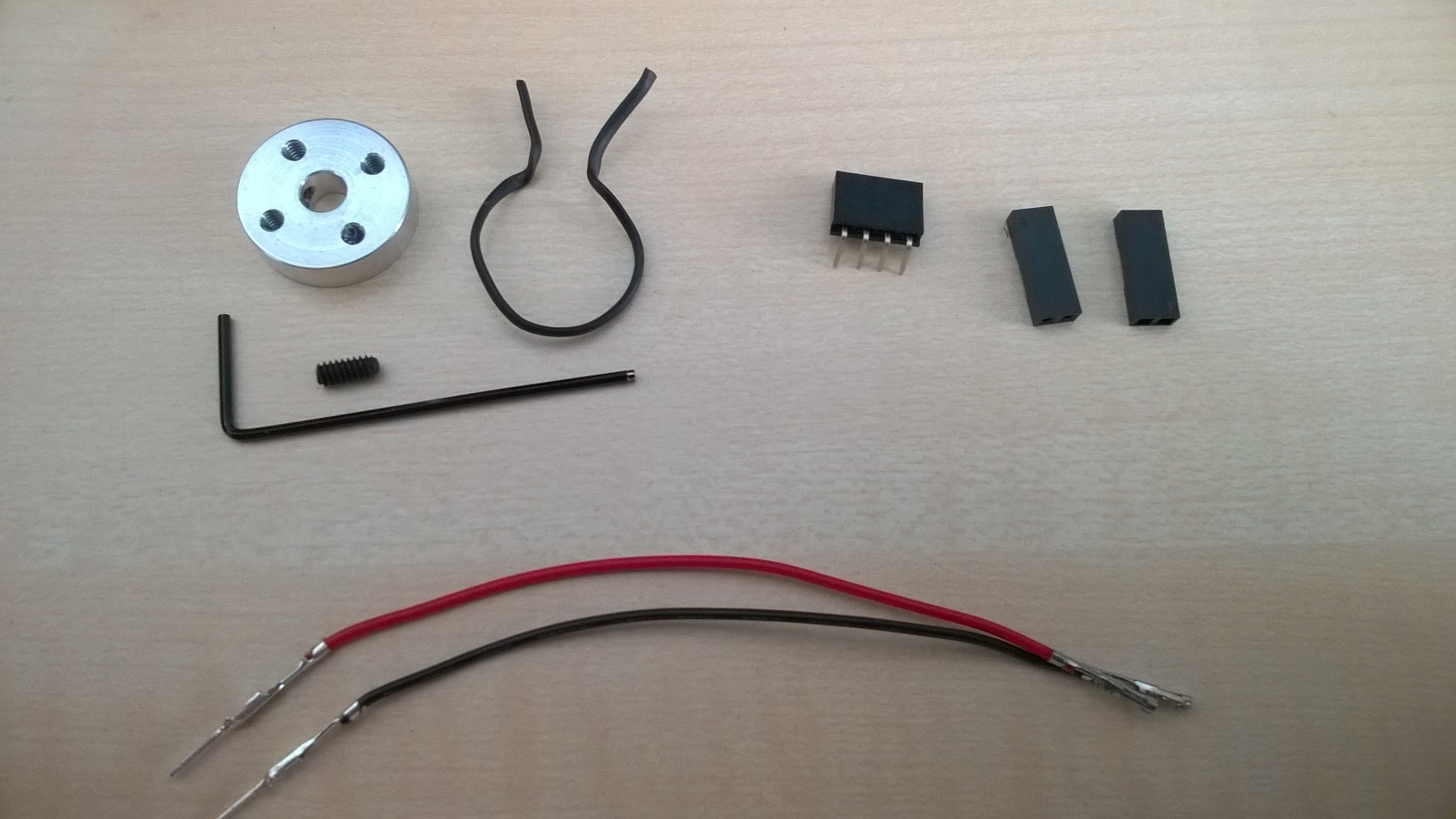
Was ist dabei was?
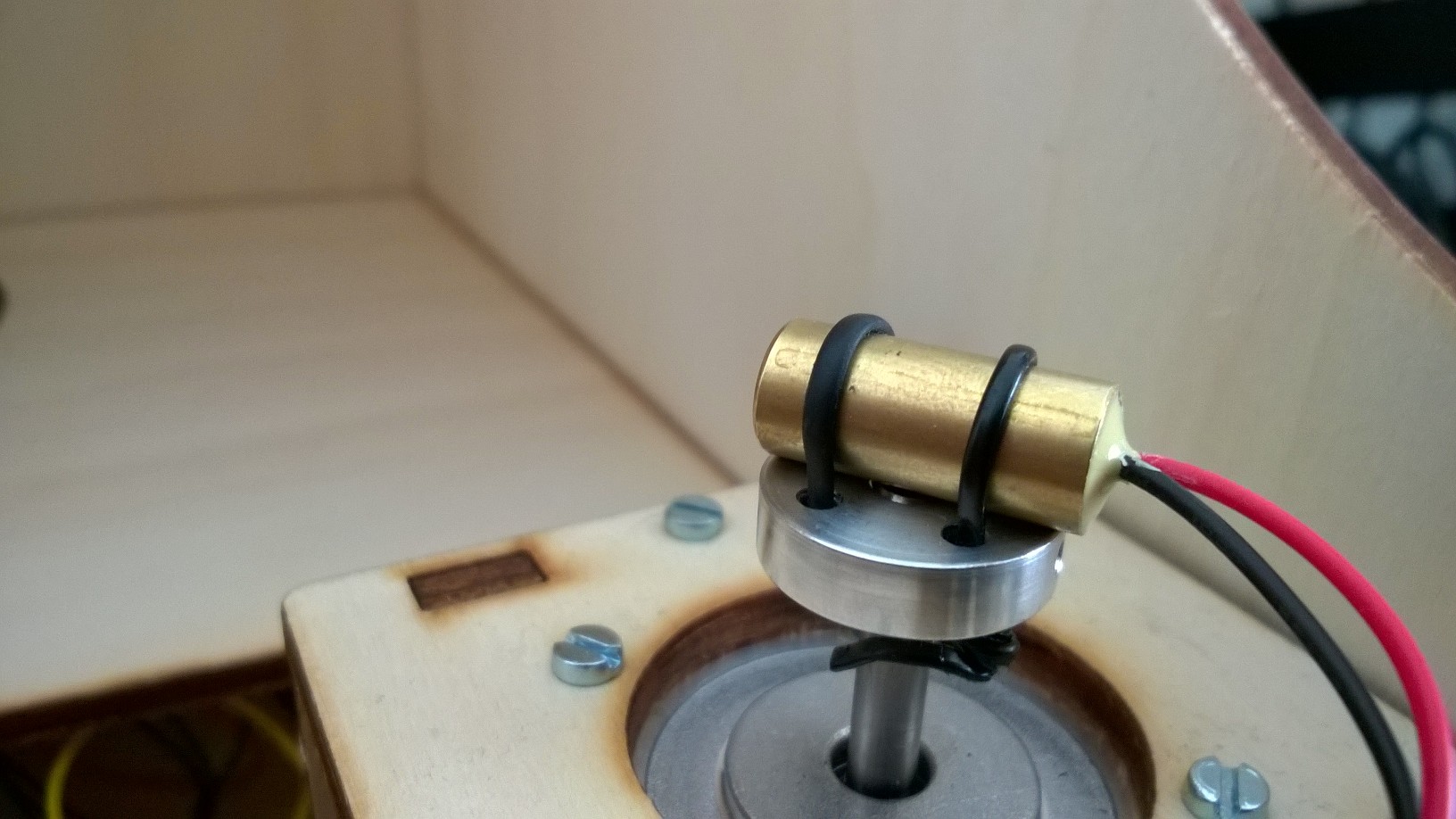
Ganz oben links ist ein Motorhalter. Mit dem mitgelieferten Miniinbus kann man den Träger direkt an die Welle des Motors schrauben.
Ich habe erst überlegt einen High-End-Halter zu designen und zu drucken um den Laser an dem Halter zu befestigen, aber mich dann für eine der schnellen Lösungen die wahrscheinlich ewig halten entschlossen. Diesmal kein Panzerklebeband. 😉 Rechts neben dem Motorhalter ist ein gummierter Draht. Durch die Schraubenhalterungen gefädelt hat das ganze bei den ersten Versuchen extrem gut gehalten…
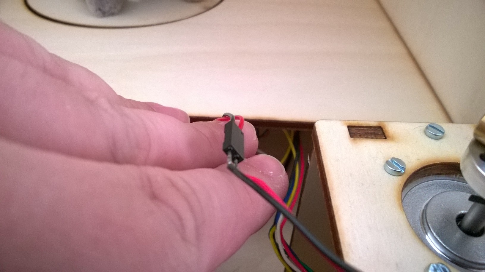
Oben rechts sind einfache Crimp Verbinder. Zusammen mit vorgekrimpten Kabeln (unten) lassen sich einfache Steckverbindungen bauen. Ich habe hierbei kürzere Kabel genommen um die zwischendrin trennen zu können.
Ach ja – das kleine Ding in der Mitte habe ich mal wieder genutzt, um die Kabel vom Motor zu verlöten und einen Stecker für den Motorshield zu haben…
Als Programm zur Ansteuerung verwende ich momentan Simple3DScan v0.1.0.
P.S. Danke übrigens dafür dass der Anschluss auf dem FabScan-Shield neben dem für den ersten Motor der für den vierten und nicht für den zweiten ist… 😉
Erst mal Danke für Progrmm und das Teilhaben lassen an den Erfahrungen und Tests! Ich experimentiere nun auch schon einige Zeit, habe wie beschrieben den Laser getauscht und mit Motor versehen.
Scanne ich damit, bekomme ich ganz, ganz viele Punkte. Die Wolke sieht allerdingst seltsam aus, wie viele einzelne ineinander verdrehte Scans … was mache ich nun damit? Mit meshlab bekomme ich auf normalem Weg (compute normals for poits sets, surface reconstruction: pioson) nix brauchbares raus.
Grüße, Willie
Ich hab´s: Nachdem ich noch mal alle alten Beiträge durchgesehen habe, fiel mir der wieder ein, mit dem Laser-Stepper, der falsch herum angeschlossen war. Das war es bei mit nicht … hier war es der Motor, der gegen den Uhrzeigersinn lief. Bei den Scans ohne Laser war das nicht aufgefallen 🙁
Jetzt habe ich Dank Deiner Software endlich einen brauchbaren FabScan. Die Qualität mit geschwenktem Laser (4) ist wirklich deutlich besser!
Grüße, Willie
Hai, first of all, thank you for the program. If I want to scan bigger object, size of volume 50x50x50 cm, what should be changed on the hardware or software? Thanks in advance.
Hi
in general if you need to scan bigger objects you will need a larger housing with bigger turntable. According to the weight of the scanned object it may be necessary to use another motor /powersource, but normally the motor shoudl be enough for light objects.
In the software you can define values for camera, turntable and laser. You start to measure from back and put the appropriate values in the software. You don’t need to resize the scanner in all directions, the laser can be put a bit nearer to the turntable, and the camera .. well it has a configurable viewing size (measure with a lineal what the camera can see from the back and put the value in the camera configuration). It is necessary that the camera can see a bit above the object to detect where the laser line is crossing the back. and obviously it must see the complete object.
If you make the housing large you will reduce the resolution of the scans (camera resolution is the same, but you have more distance to the object. A camera with higher resolution (liek from smartphone) could work, but should not be necessary for most use cases.
I tried many configuration camera-backwall distance, but it always gave me 0-byte while I set the distance > 50 cm. Then I checked filter configuration while laser was on. Laser line (red line) move continously following the highest laser point (while the highest laser point was appear-disappear repeatedly). It is located on the right of the object contour. Then I tried to get the red line to the left of the object contour by removing the roof of scanner box and combined several filter option. and yes, the red line had a fix position, but the scan result didn’t give the right form. I mean I don’t know how to scale the object. Now, I’m trying to set box similar to default configuration of camera/turntable/laser.
But, some questions ringing in my mind :
1. Is it true if I set Z value (turntable, laser, camera) measured from backwall and Y value (turntable, laser, camera) measured from top of turntable? Could I set the X of camera unequal to X of turntable?
2. Is it true if I set world width using this formula : world width = Z(camera) –
Z(turntable)?
3. What exactly safety distance used for?
4. Is the turntable radius value calculated by the software itself? This is because, its value always return to floating number with 14 numbers after the point i.e. while I set it to 6.85, if I close the software/move to another configuration (like camera, laser, etc) it will show 6.8499999xxxxxx. Is it OK leaving the value like this?
5. What is the suitable box colour that fit to red-line laser using the default filter configuration? I mean, I know your box was light-brown multiplex box. But right now I use dark-brown patterned wood, but sometimes laser line was not detected. And now I had made light-brown multiplex box. I hope this will yield satisfactory result. If it is not, maybe I will cover the box with white carton paper, what do you think about it?
Thank you for your response.
regards,
gunawan
Hi gunawan,
1. Yes according to z and y. I have never tried out other x values, but in theory it should work if the camera is aligned directly to the back wall in this case.
2. no-> Back.
3. Safety distance is a outer “ring” of the turntable where no points should be detected. So the object is only found in a circle from “center of turntable to radius minus safety distance”
4. It’s not really calculated, but you can just leave the number. The problem is how numbers are handled by computers. The program uses floating point numbers with double precision. Roughly you can say that a computer does not know real Floating Point numbers, but calculates them using exponents (there is a norm IEE 754). Think of it as the Computer could only handles powers of 2 and therfore stores numbers as Sign * 2^Exponent * Mantissa. So 6,85 would be something like + 2^129 * a very small number ( or 01000000110110110011001100110011 binary). If this value is displayed it is converted to the nearest number base 10 it could be, and that is 6.849999904632568 ( and most programs would round the displayed value back to 6.85, but compute internally with the 6.849… ). So at this point i didn’t take care for rounding of values for user friendly display and left the value like the computer would see the number.
5. A dark colour would be good for having not so much reflextions. The Fabscan Project page had some people making dark boxes for the fabscan 100 and then had problems detecting whre the laser is (independend which program was used). The program tries to detect in the upper part of the back of the box where the laser line crosses the back side. so it should be enought if there is a band which has a more reflective colour at the top where the laser is detected. You can do this easily with Maler-Krepp (sorry – don’t know the english term for this, it is a adhesive tape normally used if you e.g. paint walls, light brown or yellow colour, https://www.google.de/search?q=maler+krepp&safe=off&source=lnms&tbm=isch&sa=X&ved=0ahUKEwjdmq-It8_TAhXBPBQKHd4SCi4Q_AUIBygC&biw=1097&bih=517&dpr=1.75#spf=1 ). Also blue light can help.
Sorry if it takes some times to answer, a hell lot of comments on the web page are russian spam or buy something and it takes some time for me to find the real comments in the mail folder.
Best regards
Wolfgang
Hi Wolfgang,
Thank you for your answer. Finally, it worked. I leave the roof higher enough so the camera didn’t detect the backplane cross. The laser line on the backplane was detected as vertical line without crossing the roof. It also worked when I set the camera-backplane to 58 cm.
But I still dont understand with “world width” configuration. Then I tried 2 configuration. First, I set it to :
Z(camera) – Z(turntable)
and the result gave wrong object form. Secondly, I set it to :
Z(camera) – radius
and the result shows same form as the object. I learned from default setting that world width setting similar to second setting (based on radius). How should I set the right world width configuration?
best regard,
gunawan
World coordinates is the equivalent to width and height the camera can see in cm to convert pixels to cm. So visible size if you would put a ruler to the back.
what will we do with the *.asc file ?
what kind of sofware used to process the *.asc file ?
Sorry, i missed the comment. You can process it for example with meshlab. It is just an ASCII File with Points.
hey wolfgang
i have a question about de arduino sketch. were do i download it?
i already instalt simple 3sdscan.bud i just don’t understand were to gett the arduino sketch.
greetz jelle
Sorrry for the very late reply. It is in the SimpleSCanFirmwareDirectory. ->
Hallo,
bei meinem Arduino-Uno reagiert der A3 (Led) nicht.
Wann schaltet dieser ein?
Habe auch schon den Arduino-Uno gewechselt.
Gruß Manfred
Hallo,
bei meinem Arduino-Uno reagiert der A3-Ausgang(Led) nicht.
Habe den Arduino schon ausgetauscht, ohne Erfolg.
Gruß Manfred
Bei Start des Scans wenn vorher auf den Arduino die passende Firmware geladen wurde.